Double Ball Joint
This is going to be a monstrously long post so you might want to get comfortable.
In this post I'll be demonstrating how to make a ball and socket joint. Its quite a complex process so bare with me.
Ball joints are a more advanced method of making armatures. Unlike wire armatures, ball and sockets joints can be manipulated over and over again without wearing out and breaking. Another positive it that individual joints can be loosened or tightened to your desired tension. The down side to using ball joints is that they are time consuming and complicated to make. In the past I've made ball joints out of brass and used them in the necks of my puppets.
You can read about my old ball and socket joints HERE.
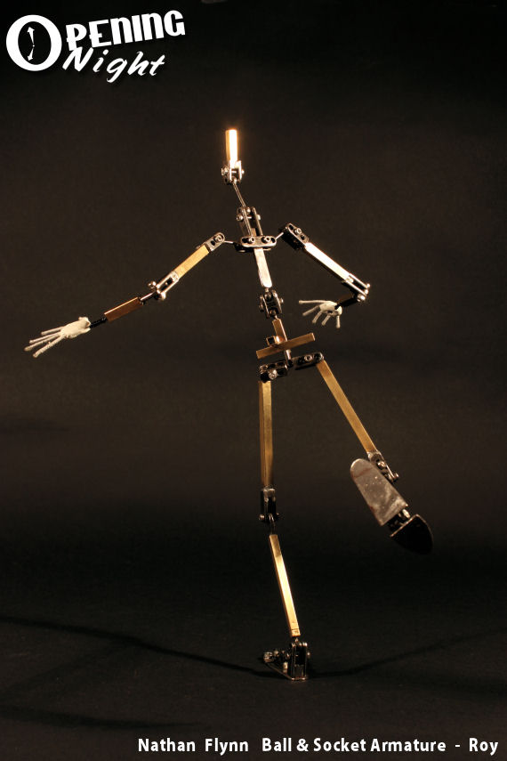
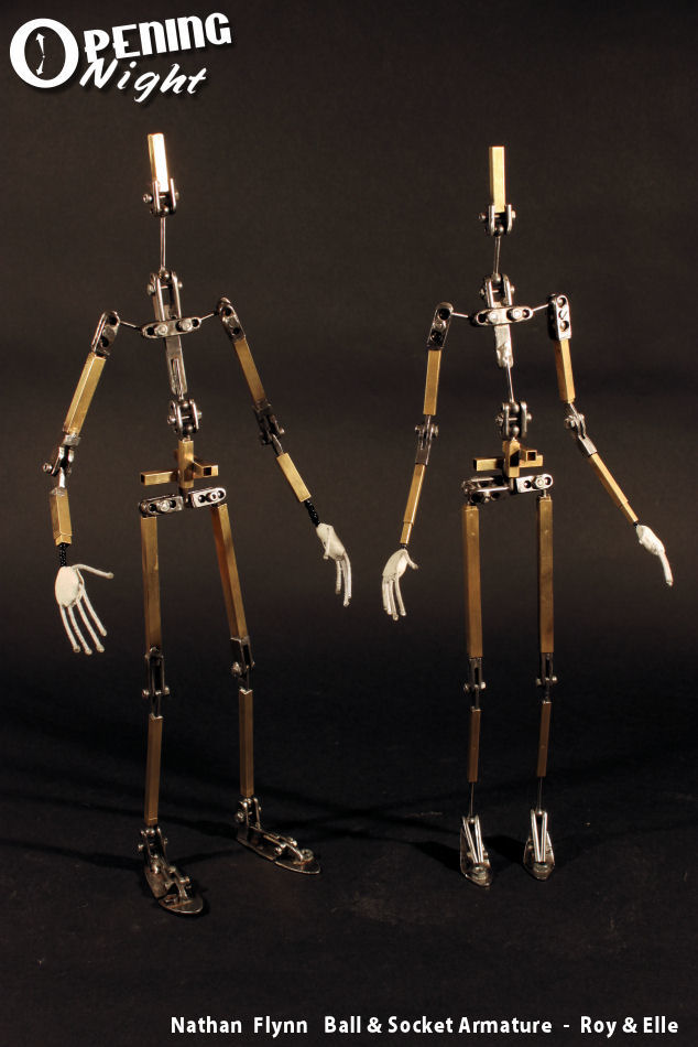
I plan to make new armatures for the characters 'Roy' and 'Elle'. This will hopefully give them a greater range of motion and I won't have to worry about wearing out the aluminium wire armature. I plan to achieve all the articulation with an mix of steel ball joints and hinges. I'm quite confident that my home made ball joints work, the challenge is making them small enough to fit inside my characters.
If you want to see some great examples of ball and socket joints then I'd recommend John Wright. His ball and socket joints are super high quality and used for many professional productions. John Wright Ball Joints can be found
HERE.
Tools & Machinery
Here are some of the tools that I will be using. Firstly a bench drill press. I recently invested in this specifically for making ball and socket joints. Its quite small so it doesn't take up too much space.
The bench drill gives a lot more control that a hand drill and most importantly it drills strait down at 90 degrees every time. This is crucial as any wobbly holes will reduce the quality of the joint. I also use a range of different sized drill bits. Its important that they are HSS (high speed steel) as they will be drilling into steel.
Above you can see a small vice I use for holding materials while I drill. Its screwed into a small wooden base so I can move it around while I'm working.
Finally, I use this rotary tool quite often at various stages. I have a collection of accessories that fit into the tool. pictured above is a reinforced cutting wheel.
Sandwich Plates
I start by making the plates that will hold the steel ball bearing. The size of the materials will vary depending on the size of the joint. Here I'm making a 5mm joint.
Above are the material for the plates. I use 6mm x 3mm steel bar (sold at B&Q in 1 meter lengths). The nuts and bolts are M2 (2mm). The bolts are called socket cap bolts and on the right is the Allen key that is used to tighten them.
I started by cutting 2 small identical lengths of steel bar with a hack saw.
Its easier to make the plates in batches so I've marked one of the bars to show where it will be divided. I will be focusing on the left section.
Next I mark where holes will be drilled. In the left hand section you can see that there will be 3 holes. the middle hole will be for the bolt and the holes either side of it will hold the ball bearings. Its best to keep all the holes central. If they are too close to an edge the joint could be wonky or weakened. I usually measure all the marks to make sure everything will line up OK.
When I'm happy with the positioning of the holes I use a center punch to put a little dent into the steel. This acts as a guide for the drill bit and locates it to the right spot. Without the center punch the drill bit would skate on the surface and drift off course.
I then clamped the two bars together making sure they lined up and the edges were flush. The blue vice holds the bars steady and the red G-clamp will stop them from separating when they are drilled.
I used a M1.5 HSS drill bit to drill a pilot hole into the steel. Its best to take your time and drill in short bursts, removing any metal filings. Its also a good idea to use cutting lubricant. After drilling the first 3 holes I re drilled them, expanding them to M2.
Once the holes where drilled I attached some of the nuts and bolts. These help to hold the 2 bars together. You don't want the bars to slip or the holes won't line up and the joint will be ruined.
I then drilled the holes for the other joints using the same method.I kept the G clamp on until all the holes where finished and I could bolt them together. The next stage was to separate the 3 joints.
Above are the 3 joints after they where cut with a hack saw. Its important not to mix up or rotate any of the plates or you might mess up the alignment. I draw black marks on the outside of each joint so I can remember how they line up. From now on I will just be showing the 3 hole joint that's at the front of the picture above.
Next I round the ends. I secure the plates in the vice with one nut and bolt tied in the middle hole.
The reinforced cutting wheel is great for cutting into the steel and shaping it. I use it on its fastest speed. Small sparks and metal specs fly from the metal so I recommend wearing goggles and a mask. ( I haven't mentioned any health and safety stuff before, but you should always take the necessary precautions when using tools and machinery).
After finishing one end I flipped the joint and rounded the other end. The rounded ends make the joints easier to handle and will give the joint more freedom to move.
Finally the plates should be complete and ready to hold some ball bearings. Above you can see the two plates loosened and separated.
Drilling & Soldering Ball Bearings
Now that the plates are ready the next stage is to drill some steel ball bearings to go in them.
For this I use 5mm stainless steel ball bearings and 1.5mm steel rod. The hardest part of this whole process is drilling ball bearings. Drilling straight into a sphere is tricky, and doing it at this scale can be a nightmare.
To hold the bearing steady I use some brass bar that has holes drilled into it. Much like the sandwich plates I just made, these will be used to clamp the ball on either side. If I tried to hold the bearing in a vice without the bars the ball would get scratched and likely spin loose when you try to drill it. Because brass is softer than steel it won't scratch the bearing.
To make the ball easier to drill I flatten the top edge. A flat surface is much easier to drill into than a curved surface. I use the cutting wheel but you could also use file.
Next I make a small dent in the centre where the hole will be drilled. This will guide the drill much line a centre punch would. To do this I use a small, pointed diamond cutting bit in the rotary tool.
Next I expand the dent using a 1mm drill bit in the rotary tool.
I then drill the bearing using a M1.5 HSS drill bit and the drill press. I once again drill in short bursts. I try to drill about 60% of the way through.
Finally I check to see if the steel rod fits. If the hole is too shallow I drill some more.
Soldering
Next the ball bearing needs to be soldered onto the steel rod. The join
needs to be really strong as the ball and rod will be under huge
pressure when secured in the joint.
Above are the tools I use. On the left is a tub of flux which is used to help the solder fuse with the metal. At the top you can see some helping hands (small metal clips) that holds things in place while I work. The yellow reel holds Silver Solder wire. Mine is an acid core solder thats designed to be used with metal. Silver Solder is much stronger than soft solder (which is designed for electrical soldering.) My solder isn't ideal as its a little bit thick. The thinner solder is best for making ball and socket Joints. You can find Solder and Flux
HERE
At the bottom of the picture is a small butane torch that's used for heating up the metal and melting the solder. Finally you can see that everything is laying on grey brick. This acts as a heat proof surface that I work on. I don't want to burn down my desk.
First I roughed up the surface of the areas that will be joined. This helps the solder stick the the metal and gives it something to grab onto. To do this I used a file. You don't want any grease or dirt on the metal or it might prevent the solder from sicking.
I then applied flux paste into the hole of the bearing and onto the end of the steel rod. I pushed the two parts together and used the helping hands to hold the parts on the surface.
Its difficult to take pictures while your soldering as my hands are busy holding the torch and the solder wire. I start by heating up the ball all around and keeping the flame moving. The white flux paste will fizz and turn clear. As this happens I dab the solder wire onto the join. The solder should melt and move around the flux into the join. The flux helps the solder to move and sometimes you can direct the solder using the heat.
The bearing will start to glow a cherry pink. Once this happens I dunk the ball into some water and quench the heat.
After drying it down it should be cool. You can see in the picture above that the metal is darker and has fire scale on it.
I use some wire wool to clean of the dirt and shine the bearing up. Now that I've completed the first ball I repeat the process to make the second ball.
Above you can see the two balls ready to be assembled between the sandwich plates. After testing if everything works I usually solder the nut onto the outside of the sandwich plate to stop it from rotating. this will mean the joint can be tightened using just the Allen key in the socket cap screw. To neaten things up I cut off the excess bolt and give everything a quick polish.
Finally the ball and socket joint is complete and ready to be played with. It's wise to test the function of the joint before incorporating it into the rest of the armature and building a puppet around it. you wouldn't want to discover that one of the soldered parts was loose after all that work.
I will be using this kind of ball and socket joint for the waist of my new armatures. Using these basic methods I will be making several different joints and I'll post details about them soon. I will probably continue with hinge joints.( Hopefully it will be a shorter post)
I hope people find this useful.
Thanks for reading.